| Author |
 Topic Topic  |
|
Tone
United Kingdom
36 Posts |
 Posted - 09 Nov 2019 : 19:55:35 Posted - 09 Nov 2019 : 19:55:35


|
Hi All, Should a rev counter work if you have it out of the dash, connect a wire from the + side of coil around the“ pulse”connection on the back of the Rev counter to battery+
Then another wire from battery + to spade on back of Rev counter?
Then start car! Or is there any other way of bench testing?
As you can probably tell I’m not an electrician! So any help would be gratefully received.
Cheers Tone. |
|
|
Panky
United Kingdom
70 Posts |
Posted - 09 Nov 2019 : 22:14:30


|
Pretty sure the connection to the coil should be to the -ve terminal (if negative earth) and posibly a chasis ground connection too from somewhere on the gauge.
Your gauge should connections be shown on here somewhere, click on the 'How do I wire up my Tachometer' link from the FAQ's
https://speedycables.com/faqs/ |
Edited by - Panky on 09 Nov 2019 22:17:55 |
 |
|
|
Sunbeam-mike
United Kingdom
164 Posts |
Posted - 10 Nov 2019 : 10:14:01
|
Hi
Surely the diagrams in the link are wrong.
As Tone mentioned our tachos have a 'pulse' loop inside the tacho.
the 'RVI' tachos shown are not the same.
Try this:
https://www.sw-em.com/Smith%27s%20Tachometer.htm
It's a bit of a long read but basically explains that you power the tacho with 12v and then wire the pulse loop in line with the ignition-to-coil wire separately.
To bench test you would have to rig up a circuit to generate current (1 Amp?) pulses through this loop.
Mike Hooper |
|
|
|
pruyter
Netherlands
320 Posts |
Posted - 10 Nov 2019 : 11:02:16
|
Hi Tone,
I have just read your post and indeed there are a few checks to made before you start taking things apart. At first, as Panky suggested, check if the wires on the coil are installed at the right posts. So the plus side (or SW-side) is connected to the contact switch while the negative (or CB-side) side is connected to the distributor i.e. the contact breaker points. The car will run while the wires are wrongly connected but the engine will not run efficiently.
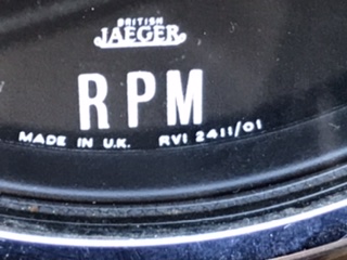
Secondly check if the rev counter is ment for negative earth as it should in a Rapier series V. It is possible that a former owner has changed the rev counter unintentionally for one with positive earth (as for instance installed in a Rapier series IV). This check is an easy one, because on the front dial plate you can see the text "negative earth" or "positive earth").
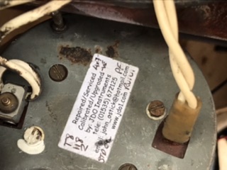
The next check is to make sure the wire loop on the backside of the rev counter is placed in the appropiate direction.
Finally check if the metal bride on the backside of the rev counter (in which the wire loop is installed) has very good contact between its "legs" and the backside of the rev counter. This last possible culprit is a common one.
When this checks are not solving the problem than you can check with a Voltmeter if there is some failure in the connection from the contact switch via the rev counter to the coil and/or from the coil to the distributor.
Regards,
Peter |
Edited by - pruyter on 10 Nov 2019 11:05:52 |
|
|
|
Tone
United Kingdom
36 Posts |
Posted - 10 Nov 2019 : 12:56:40
|
Thanks guys, The wiring diagram I have shows a negative earth system, and the pulse wire going on the + positive side of the coil, yet you guys say it goes on the - negative side! I’m confused.
Cheers Tone.. |
|
|
|
Tone
United Kingdom
36 Posts |
Posted - 10 Nov 2019 : 13:12:04
|
Am I right in thinking that you have a wire from the ignition warning light to the spade fitting on the Rev counter, then going on to terminal 2 on the ignition switch, then the pulse wire from terminal 2 to the loop on the Rev counter to the - neg side of the coil, then a wire from the + poss side of the coil to a switched live ( 2 on ign switch?)
|
|
|
|
Tone
United Kingdom
36 Posts |
Posted - 10 Nov 2019 : 14:58:07
|
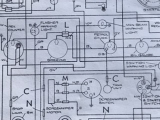
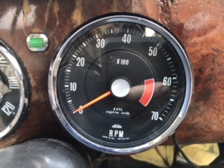
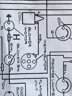
Me again, sorry, I have included the wiring diagram and Rev counter ( RVI ) ? This is how the car is wired up.
There is a sticker on the back stating it’s den calibrated etc.
Does this make any sense?
|
|
|
|
Panky
United Kingdom
70 Posts |
Posted - 10 Nov 2019 : 14:58:44
|
This might help if your gauge is shown. I think the dotted line on the Smiths diagram means that wire is removed if reto-fitting the gauge
 |
|
|
|
Tone
United Kingdom
36 Posts |
Posted - 10 Nov 2019 : 15:00:12
|
|
|
|
|
Tone
United Kingdom
36 Posts |
Posted - 10 Nov 2019 : 15:02:22
|
|
|
|
|
pruyter
Netherlands
320 Posts |
Posted - 10 Nov 2019 : 15:06:54
|
In WSM 145, section N (Electrical equipment) you can see on page 61 a wiring diagram for your Rapier series V.
Studying this diagram shows a white wire going from the contact switch to the rev counter and this wire continues as a white wire to the warning light. From the rev counter a white wire is going to the plus of the coil. From the negative side of the coil a white wiring is going to the rev counter to the same connection from where the white wire to the warning light is going. Finally a black wire is going from the rev counter to earth. to the plus of the coil. From the negative side of the coil a white wiring is going to the rev counter to the same connection from where the white wire to the warning light is going. Finally a black wire is going from the rev counter to earth.
Please buy WSM 145 if you don't have done this already and when you already possess this WSM read it!
Regards,
Peter |
|
|
|
Tone
United Kingdom
36 Posts |
Posted - 10 Nov 2019 : 15:09:16
|
|
|
|
|
pruyter
Netherlands
320 Posts |
Posted - 10 Nov 2019 : 15:11:01
|
At least the right rev counter is installed! Negative earth as it should be.
Did you made the checks as mentioned in my earlier post? |
Edited by - pruyter on 10 Nov 2019 15:12:26 |
|
|
|
Tone
United Kingdom
36 Posts |
Posted - 10 Nov 2019 : 15:18:54
|
| I have got a paper manual! And as you say on page 61, it does show the rapier diagram, and my car seems to be wired up the same, with the pulse wire going to + on the coil and the - a white/ black wire to the distributor. It’s just that everyone tells me that the pulse wire should go to the - on the coil! When I put the wire onto the - side of the coil, and turned on the ignition the amp meter showed an instant discharge. |
|
|
|
Tone
United Kingdom
36 Posts |
Posted - 10 Nov 2019 : 15:26:23
|
Funny I can only see a white/black wire coming off the negative side of the coil to the distributor, there is not another white wire going back to the Rev counter on my car or on the wiring diagram on page 61. Or am I going mad! |
|
|
|
Tone
United Kingdom
36 Posts |
Posted - 10 Nov 2019 : 15:29:31
|
|
|
|
|
Topic |
|